
Panel Mount Printer Integration: How to Design the Cutout, Mounting and Service Space

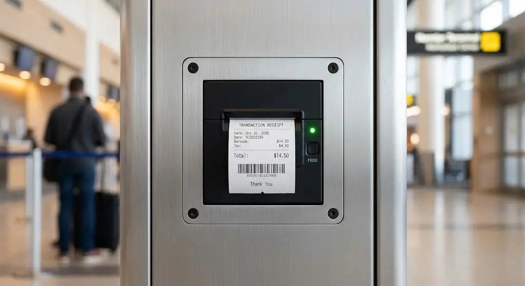
A mechanical drawing says a panel printer is 137 mm wide. That does not mean the equipment needs a 137 mm opening.
The overall printer size, front bezel, panel cutout, mounting points and space required behind the panel describe different parts of the installation. Mixing them up is an easy way to end up with a finished sheet-metal panel that needs to be reworked.
This becomes especially important when a panel printer is integrated into a kiosk, payment terminal, industrial instrument or other OEM equipment. Once the front panel has been cut, bent, coated and assembled, changing the printer installation becomes much more expensive than changing a CAD drawing.
Before releasing the enclosure drawing, the mechanical engineer should be able to answer five practical questions:
- What is the exact panel cutout?
- How is the printer fixed to the panel?
- How much space is really required behind it?
- Can the paper be replaced without removing nearby hardware?
- Can the printer itself be removed later for maintenance?
These questions are the starting point for reliable panel mount printer integration.
1. Start with the Mechanical Drawing, Not the Product Photo
A product photo is useful for understanding what a printer looks like. It is not enough to manufacture the equipment panel around it.
Even the overall dimensions shown in a datasheet have a different purpose from the installation dimensions.
| Drawing Item | What the Engineer Uses It For |
|---|---|
| Overall dimensions | Check the physical envelope of the printer |
| Panel cutout | Define the opening in the equipment panel |
| Mounting points | Locate screws, brackets or retaining structures |
| Installation depth | Check how far the printer extends behind the panel |
| Connector position | Reserve room for plugs and cables |
| Service clearance | Allow paper loading, opening, cleaning and removal |
This distinction appears in real panel-printer designs. Manufacturer documentation may specify the printer dimensions and installation geometry separately, because the front structure and the body passing through the panel are not necessarily the same size.
For an OEM project, the safest source is therefore the model-specific mechanical drawing or 3D model, followed by verification with an actual sample before production.
2. Do Not Create the Panel Cutout from Overall Printer Dimensions
Suppose the front bezel is wider than the body that passes through the panel.
The overall width includes the bezel, but the cutout obviously cannot be based on that width alone. The bezel may need to sit against the front surface while a smaller section of the printer passes through the opening.
The opposite mistake is also possible. An engineer may concentrate on the main body dimensions but overlook:
- mounting tabs;
- screw locations;
- cover movement;
- a connector extending from the rear;
- a protruding mechanism;
- clearance needed during insertion.
This is why a proper mechanical review should identify at least three different envelopes:
the part visible from the front, the part passing through the panel, and the part occupying space inside the enclosure.
They may overlap, but they serve different purposes.
When SNROKIOSK provides a STEP/STP model or mechanical drawing for a selected printer, use that file to build the enclosure model. Do not recreate the mounting geometry from dimensions copied from a product-page image.
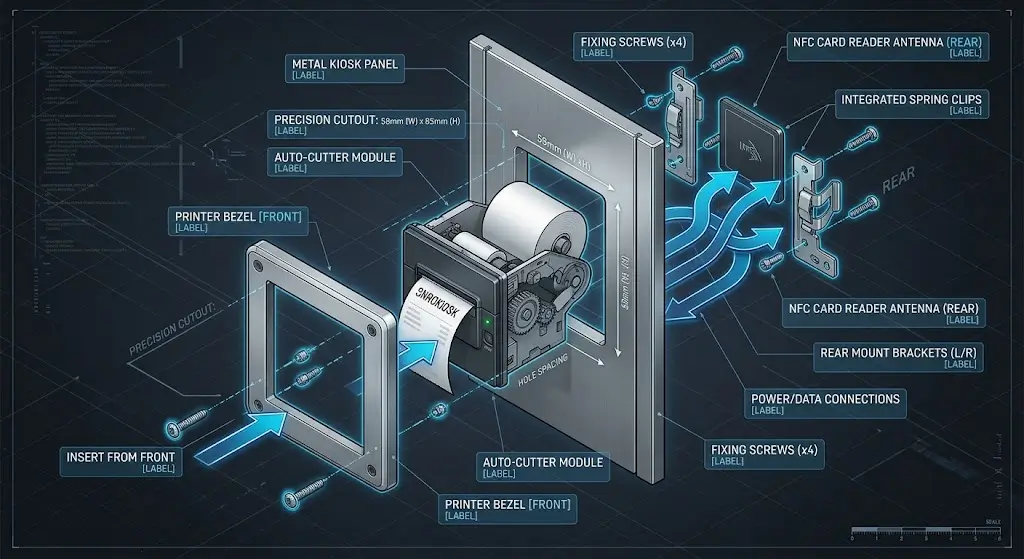
3. Panel Thickness Is Part of the Mounting Design
Panel thickness is easy to ignore because it may not change the rectangular opening itself.
It can still change the installation.
Consider a printer with a front flange and a retaining structure behind the panel. Increasing the sheet thickness changes the distance between those two mounting surfaces. Depending on the design, it can affect screw engagement, bracket position or how the front bezel sits against the enclosure.
Manufacturer instructions illustrate why this is model-specific. Citizen’s CBM-290/291 installation instructions specify a particular rack-panel thickness range for that printer and also instruct the installer to verify that the front cover opens and closes properly after mounting.
That number should not be reused for another printer. The useful lesson is the opposite: panel thickness should be checked against the mechanical specification of the exact model being installed.
For a new enclosure, confirm:
- panel material;
- finished panel thickness;
- mounting method;
- screw engagement;
- front-bezel seating;
- rigidity around the cutout.
If the enclosure changes from a thin sheet-metal prototype to a thicker production panel, recheck the installation instead of assuming the same mounting hardware will behave identically.
4. The Space Behind the Panel Is More Than Printer Depth
A CAD check often starts by measuring the printer body against the internal cabinet depth.
That is necessary, but incomplete.
Imagine that the printer body fits with 8 mm to spare. Then the electrical engineer connects a power plug and an RS232 or USB cable to the rear of the printer.
The connector itself consumes some of that 8 mm. The cable also needs room to leave the connector without being crushed against a bracket or the back wall.
The real installation envelope may therefore look more like this:
Front Panel → Printer Body → Connector → Cable Bend → Internal Structure
There may also be another device behind or beside the printer: an industrial PC, payment module, power supply, scanner or wiring harness.
The result is a common prototype problem: the printer fits, but the assembled printer does not.
When checking installation depth, include the actual connector orientation and cable routing. If the selected model has side-facing connectors, check lateral clearance as well.
This is one reason a 3D printer model is useful but not sufficient on its own. Unless the CAD assembly also includes realistic connectors and cable space, it can make the enclosure look less crowded than the physical machine will be.
5. Paper Loading Can Change the Service Design
Paper replacement is a moving operation, not a static dimension.
A printer may fit perfectly behind the front panel while closed, but the cover may hit the touchscreen frame, payment terminal, cabinet trim or another module when someone tries to open it.
This problem is difficult to see if the mechanical review checks only the printer’s closed dimensions.
For each candidate printer, ask:
- From which direction is the paper loaded?
- Which part of the printer opens?
- How far does that part need to move?
- Is the roll inserted from the front or from inside the equipment?
- Does another component obstruct the operator’s hand?
- Does the complete kiosk need to be opened before paper can be replaced?
There is no universally correct access direction. A front-access design can work very well in one terminal, while a locked rear service door may make more sense in another.
What matters is that the maintenance workflow is designed intentionally.
A paper compartment that opens easily on a workbench can become awkward once the printer is surrounded by the final enclosure.
That should be discovered during prototype assembly, not after the first batch of cabinets arrives.
6. Check the Cutter and Paper Exit in the Actual Panel
The front of the printer also needs working space.
The surrounding panel or decorative trim should not interfere with the receipt after printing and cutting. Manufacturer installation guidance for panel/rack printers specifically warns against placing obstructions in front of the output/cover area because they can interfere with paper ejection.
During the prototype stage, print the actual type of receipt expected in the application rather than only running a short test page.
Look at:
- whether the receipt exits cleanly;
- whether the panel edge touches the paper;
- whether curled paper catches around the outlet;
- whether the user can grasp the receipt naturally;
- whether the cover and cutter area remain accessible for maintenance.
This is different from designing a printer that sits deeper inside a kiosk and sends paper through a separate cabinet outlet. That architecture introduces a longer paper path between the printer and the user.
For that type of installation, our kiosk printer paper exit design guide covers the paper-path problem in more detail.
7. Plan Power and Data Cables Before Freezing the Sheet Metal
Cable routing deserves its own check because panel printers sit at the boundary between the front panel and the internal electronics.
Depending on the selected model, the host communication path may use USB, RS232 or another supported interface. Power requirements should be checked separately against the printer documentation.
Do not assume that a USB communication connection automatically means the printer is powered from USB.
Citizen’s general printer architecture guidance, for example, treats the host, printer and printer power source as separate parts of a printing system.
Inside the equipment, check where each cable goes after leaving the printer.
A good layout should avoid:
- sharp cable bends immediately behind a connector;
- cables trapped by a cover or bracket;
- tension on connectors;
- wiring crossing a moving paper cover;
- connectors that cannot be reached after neighboring modules are installed.
Also consider removal.
If a technician needs to replace the printer, can the power and communication cables be disconnected first? Or is the connector hidden behind another component that must be removed?
That difference may not matter during the first assembly. It matters every time the machine is serviced.
8. Installation Access and Maintenance Access Are Different
A printer can be easy to install on the production line and difficult to replace in the field.
Consider this assembly sequence:
- Install the panel printer.
- Connect its cables.
- Install an internal support bracket.
- Install the controller behind the bracket.
- Close the enclosure.
That may be perfectly efficient during production.
Six months later, however, a technician who needs to remove the printer may discover that the controller and support bracket must come out first.
This does not automatically make the design wrong. Sometimes packaging constraints require that arrangement.
But it should be a conscious decision.
During prototype review, perform the maintenance operations that will actually happen:
- replace the paper roll;
- open the printer cover;
- clear the accessible paper path;
- disconnect the cables;
- remove the printer;
- reinstall it;
- reconnect it and print again.
The last three steps are particularly useful. Many prototypes are tested only by installing the printer once and confirming that it prints.
Removal tells you much more about serviceability.
9. 58mm vs 80mm Is Also a Mechanical Decision
Paper width is normally discussed in terms of receipt layout, but changing from a 58mm printer to an 80mm printer can affect much more than the printed content.
Depending on the models being compared, it may change:
- front-panel space;
- panel cutout;
- printer body dimensions;
- paper-roll space;
- installation depth;
- cover movement;
- cable position;
- maintenance access.
This is why the paper-width decision should be made early.
SNROPRINTER already has separate selection guidance covering 58mm versus 80mm printers and compact kiosk applications, so there is little value in repeating that buying discussion here.
From a mechanical-integration perspective, the important point is simpler:
if the printer model or paper-width architecture changes after the enclosure has been frozen, reopen the mechanical review.
Do not assume that the existing cutout and internal space remain valid.
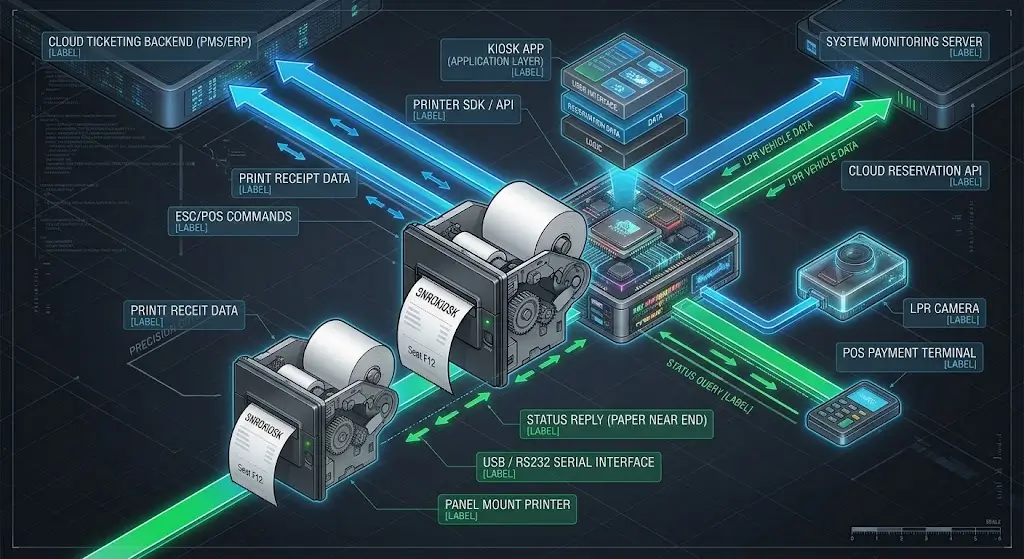
10. A Mechanical Fit Does Not Confirm Software Compatibility
At some point the mechanical engineer hands the prototype to the electrical and software teams.
A printer that fits the panel can still be the wrong printer for the host system.
Before approving the model for production, confirm the applicable:
- communication interface;
- host operating system;
- driver;
- SDK/API;
- command or protocol resources;
- required printer-control functions.
These belong to a different integration layer from the panel cutout.
For example, two printers may both physically fit the available opening but require different software resources from the host application.
If your project is still defining this part of the architecture, see our kiosk printer SDK vs driver vs ESC/POS integration guide and the applicable SDK & API resources for the selected model.
11. Prototype with the Actual Printer Before Production Tooling
A STEP file can answer many interference questions before metal is cut.
It cannot tell you whether changing the paper roll feels awkward with a payment terminal 40 mm away. It cannot reproduce the stiffness of a cable harness. It also cannot show every assembly variation that appears when the physical parts are manufactured.
For a new OEM enclosure, a practical validation sequence is:
Select the printer
→ Obtain the mechanical drawing / 3D model
→ Design the cutout and mounting structure
→ Build the prototype panel
→ Install the actual printer
→ Connect real power and data cables
→ Load the intended paper roll
→ Print and cut representative receipts
→ Replace the paper
→ Remove and reinstall the printer
→ Freeze the production drawing
The remove and reinstall step is worth keeping.
It forces the prototype team to test the design from the perspective of the future service technician, not only the original assembler.
For SNROKIOSK models with mechanical files available, our 3D Drawings section can be used during enclosure development.
12. Prototype Fit Does Not Automatically Mean Production Fit
The prototype finally fits. The printer opens properly, cables are accessible and the receipt exits cleanly.
There is still one more question before production:
How much variation can the design tolerate?
A production enclosure introduces manufacturing variables such as:
- cutout tolerance;
- mounting-hole position;
- sheet-metal bending;
- coating or paint;
- panel flatness;
- assembly variation.
The printer itself also has its own mechanical specification and manufacturing tolerance.
This is why a prototype that requires parts to be pushed, flexed or aligned precisely by hand is worth reviewing again before volume production.
The objective is not to make the opening unnecessarily large. Excessive clearance can create its own alignment or appearance problems.
Instead, the printer mechanical specification and the enclosure supplier’s manufacturing capability should be reviewed together. The final production drawing should define a repeatable assembly, not merely reproduce the dimensions of one successful prototype.
Panel Printer Options for OEM Equipment Integration
SNROKIOSK offers 58mm and 80mm panel printer options for self-service terminals, industrial equipment and OEM machines.
For projects requiring 80mm receipt output, models such as SNR-EP8305 and SNR-EP8303 can be evaluated according to the required panel structure, paper access, interface and available installation space.
For more compact 58mm applications, SNR-EP5804 and SNR-EP5809 provide alternative panel-printer directions.
The product model should not be selected from paper width alone. The mechanical drawing, panel cutout, paper-loading method, host interface and service workflow should all be checked before the enclosure is finalized.
Detailed specifications belong on the individual product pages. For enclosure design, request the applicable mechanical drawing or 3D model for the exact printer version being evaluated.
Mechanical Review Checklist Before Releasing the Enclosure Drawing
Before sending a panel design for tooling or batch fabrication, review it with the actual printer in mind.
| Check | What to Verify |
|---|---|
| Printer version | Drawing matches the hardware being purchased |
| Panel cutout | Uses model-specific installation dimensions |
| Panel thickness | Compatible with mounting structure |
| Mounting points | Holes/brackets align without forcing the printer |
| Rear clearance | Includes connectors and cable routing |
| Paper access | Cover can open and roll can be replaced |
| Paper exit | Surrounding panel does not obstruct output |
| Power connection | Correct supply and accessible connector |
| Data connection | Correct interface and accessible connector |
| Maintenance | Printer can be removed without unnecessary disassembly |
| Prototype | Actual printer has been installed and operated |
| Production tolerance | Enclosure manufacturing variation has been considered |
If several of these items are still unknown, the panel drawing is probably not ready to freeze.
FAQ
Is panel cutout size the same as printer dimensions?
No. Overall printer dimensions describe the physical envelope of the printer. The panel cutout defines the opening required for installation and depends on the printer’s front structure and mounting design. Use the mechanical drawing for the exact model.
How much space should I leave behind a panel printer?
Allow for more than the printer body itself. The installation may also require space for power and data connectors, cable routing and service access. The exact requirement depends on the selected printer and enclosure.
Does panel thickness affect panel printer installation?
It can. Panel thickness may affect mounting brackets, screw engagement, bezel seating and other parts of the fixing structure. Check the specified installation requirements of the exact printer rather than applying a general thickness rule.
Should I select the panel printer before designing the enclosure?
Preferably, yes. The selected printer affects the cutout, mounting points, installation depth, paper access, cable routing and service space. Changing the printer after the enclosure is finalized can require mechanical redesign.
Can a 3D model confirm that the printer will fit?
A 3D model is very useful for checking geometry and interference, but physical prototype testing is still recommended. Real connectors, cables, paper loading and maintenance operations can reveal problems that are easy to miss in CAD.
What should I test before mass production?
Install the actual printer in a representative enclosure and test paper loading, printing, cutting where applicable, receipt output, cable access, cover movement and printer removal/reinstallation. Also review production tolerances before releasing the final enclosure drawing.
Design the Panel Around the Real Printer
A panel printer becomes part of the enclosure as soon as its cutout and mounting points are added to the drawing.
That makes the mechanical documentation just as important as the headline printer specifications.
For a new project, select the printer early enough to obtain its drawing, put the real geometry into the enclosure design, and test an actual unit before the sheet-metal design is released for production.
A few extra checks at the prototype stage are much cheaper than modifying a finished batch of panels.
If you are evaluating an SNROKIOSK panel printer, send us the printer model, equipment layout or panel drawing, required paper width and host platform. We can provide the applicable product information, mechanical resources and software integration documents available for the selected model.