
Card Dispensing Kiosk Hardware Architecture: Designing the Card Path from Hopper to User
A practical engineering guide to card-dispensing kiosk architecture, covering the card path, dispenser, reader or encoder, host controller, reject and recycle logic, maintenance access, and software responsibility boundaries.

A card dispenser is only one part of a card-issuing kiosk.
In a real self-service terminal, the card may leave a hopper, stop at an RFID reader or a third-party encoder, wait for the application to make a decision, move toward the user, or be diverted into a reject or collection path.
The difficult part is rarely making one card move.
The difficult part is making sure every piece of hardware agrees on where the card is, what has already happened to it, and where it should go next.
For kiosk manufacturers and system integrators, that leads to a more useful design question:
What hardware blocks are required between the card hopper and the final card output, and which system is responsible for each decision?
A practical card-dispensing kiosk normally combines the card handling mechanism, reader or encoder, host controller, power supply, physical card path, sensors, output or collection mechanism, and the kiosk application coordinating the transaction.
Quick Answer: What Does a Card Dispensing Kiosk Architecture Look Like?
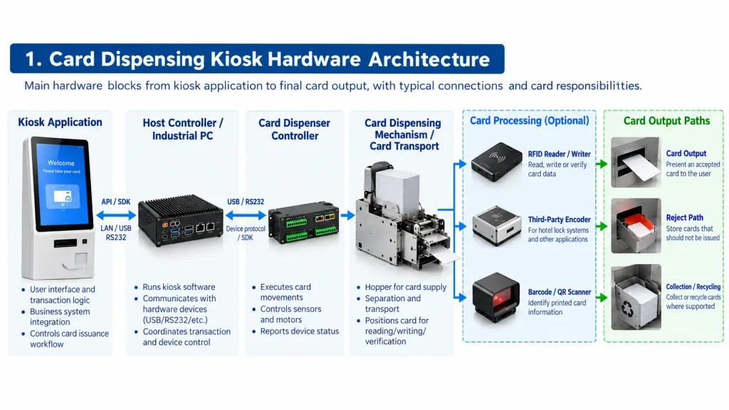
A typical architecture can be viewed as:
Kiosk Application → Host Controller / Industrial PC → Card Dispenser Controller → Card Transport → Reader / Encoder / Scanner → Output / Reject / Recycle → User
Not every project needs every block.
A simple access-card terminal may only dispense pre-programmed cards. A hotel self-check-in kiosk may need to stop the card at a door-lock encoder before issuing it. A telecom kiosk may identify a SIM card using a barcode or chip-reading process. A parking system may issue a card at entry and collect it again later.
The architecture should therefore be designed around the complete card workflow, not around the dispenser specification alone.
If you are still at the hardware-selection stage, start with our card dispensers for self-service kiosks before narrowing the design to a specific mechanism.
Start with the Card Workflow, Not the Product Model
Before selecting a dispenser, describe what must happen to one physical card during a normal transaction.
A typical flow might be:
Card available → Card separated from hopper → Card moved to processing position → Card read, written or verified → Application decides result → Card presented, rejected, collected or recycled
That simple sequence usually exposes the important design decisions much faster than comparing product datasheets.
Does the card only need to be issued?
Does it need to be read or encoded during the transaction?
If the write operation fails, can the card still be delivered?
Does a returned card go into a collection box, or does it need to be reused?
What happens if the card has already left the hopper when power is interrupted?
These questions should be answered before the kiosk enclosure is finalized.
We often see projects where the dispenser itself fits perfectly in CAD, but the card workflow changes later. Once an encoder, reject path or larger hopper has to be added, the original enclosure suddenly has no room for cable access, card recovery or routine maintenance.
Changing the dispenser during the prototype stage is manageable. Changing the card path after the cabinet tooling or sheet-metal structure has been finalized is much more painful.
The Main Hardware Blocks
It is easier to design a card-dispensing kiosk when the system is separated into functional blocks.
| Hardware Block | Main Responsibility |
|---|---|
| Card Hopper | Stores cards available for issuing |
| Dispensing Mechanism | Separates and transports one card |
| Reader / Writer / Encoder | Reads, writes, verifies or personalizes card data |
| Barcode / QR Scanner | Identifies printed card information where required |
| Host Controller / Industrial PC | Connects kiosk software with the hardware devices |
| Device Controller | Executes supported card movements and reports hardware status |
| Sensors | Detect card position, hopper condition and mechanism state |
| Card Output | Presents an accepted card to the user |
| Reject / Collection Path | Stores cards that should not be issued |
| Recycling Path | Returns reusable cards to a reusable card flow where supported |
One product may combine several of these blocks. Another project may use them as separate devices.
An integrated RFID card dispenser combines card transport with a reader/writer. A hotel project may instead use a dispenser with the customer’s own room-key encoder. A multi-hopper terminal adds another decision before the card even enters the transport path: which hopper should supply the card?
Architecture 1: Dispense-Only Kiosk
The simplest structure is:
Kiosk Application → Card Dispenser → User
The cards are prepared before being loaded into the hopper. The dispenser only needs to separate one card, move it through the mechanism and present it to the user.
This reduces the number of devices inside the kiosk and can simplify integration.
However, dispense-only does not mean failure-free.
The project still needs to consider double feeding, empty or low-card conditions, a card stopping before the outlet, sensor abnormalities and recovery after interruption.
A useful rule during prototype testing is to avoid testing only the successful dispense cycle. Run the mechanism with a nearly empty hopper, different card batches and repeated power-on / power-off conditions as well.
Architecture 2: Dispenser with an Integrated Reader or Writer
A more integrated structure looks like this:
Kiosk Application → Card Dispenser Controller → Card Positioning → Integrated Reader / Writer → Application Decision → Card Output
The mechanical advantage is obvious: the card stopping position and reader location can be designed as one assembly.
This architecture is suitable for supported RFID, contact IC or magnetic-card applications.
The important engineering point is that mechanical success and data-processing success are two different events.
A card can reach the correct position while a read or write operation still fails.
Card positioned successfully does not mean card personalization completed successfully.
The next movement should depend on the actual processing result returned by the reader or the host application.
For the reader side of the architecture, see our dedicated guide to card reader and card dispenser integration.
Architecture 3: Dispenser with a Customer-Supplied Encoder
Some applications cannot use a generic integrated reader.
Hotel key-card systems are a good example.
The architecture may become:
Kiosk Application → Card Dispenser → Card Stops at Hotel Encoder → Key Encoding → Verification → Present or Reject Card
This is where mechanical details become just as important as the communication protocol.
In hotel projects, we normally want to know the exact encoder model before the dispenser layout is frozen.
The reason is simple: encoder dimensions alone are not enough.
The actual antenna or contact area has to align with the card stopping position. The reader-to-card distance may also matter, particularly with RFID-based hotel encoders.
An encoder can physically fit inside the dispenser and still fail to operate reliably if the active reading area is too far from the card.
Cable direction, encoder replacement and service access also need to be considered.
For systems using ASSA ABLOY/VingCard, SALTO, dormakaba or other hotel lock platforms, the customer’s compatible encoder is normally installed in the reserved card-processing area of the dispenser.
SNROKIOSK supplies the card-handling hardware, communication resources and mechanical integration support. The customer’s software team or hotel-system partner remains responsible for PMS integration, lock-system software and the overall check-in transaction logic.
More detail is available in our hotel key card encoder integration guide and hotel self check-in kiosk hardware integration page.
Architecture 4: Multi-Hopper Card Dispensing
A dual-hopper or multi-hopper system introduces a new decision before the card starts moving:
Transaction Result → Select Hopper → Dispense Card → Process Card → Present / Reject
This is useful when one kiosk needs to issue different card types, service levels, SIM variants or other card-based products.
Dual-hopper designs such as the SNR-CD2604J-M7S allow the host application to choose between separate card supplies. Depending on the project configuration, the card-processing path may also incorporate RFID reading/writing or barcode / QR identification.
Six-hopper platforms such as the SNR-CD2604J-6R are designed for projects where several card types must be available inside the same unattended terminal.
The number of hoppers is only part of the design problem.
Service access matters just as much.
One practical issue we often discuss with integrators is hopper loading direction.
Rear loading can look attractive in CAD because it reduces the vertical clearance required above the unit. That can work well with a single hopper. With several hoppers arranged in front-and-back rows, however, the front modules may block access to the rear ones.
A compact design on the drawing can therefore become awkward for the technician who has to refill or remove the cards later.
Always review hopper loading with the complete kiosk layout, not just the dispenser dimensions.
Design the Physical Card Path Before Finalizing the Cabinet
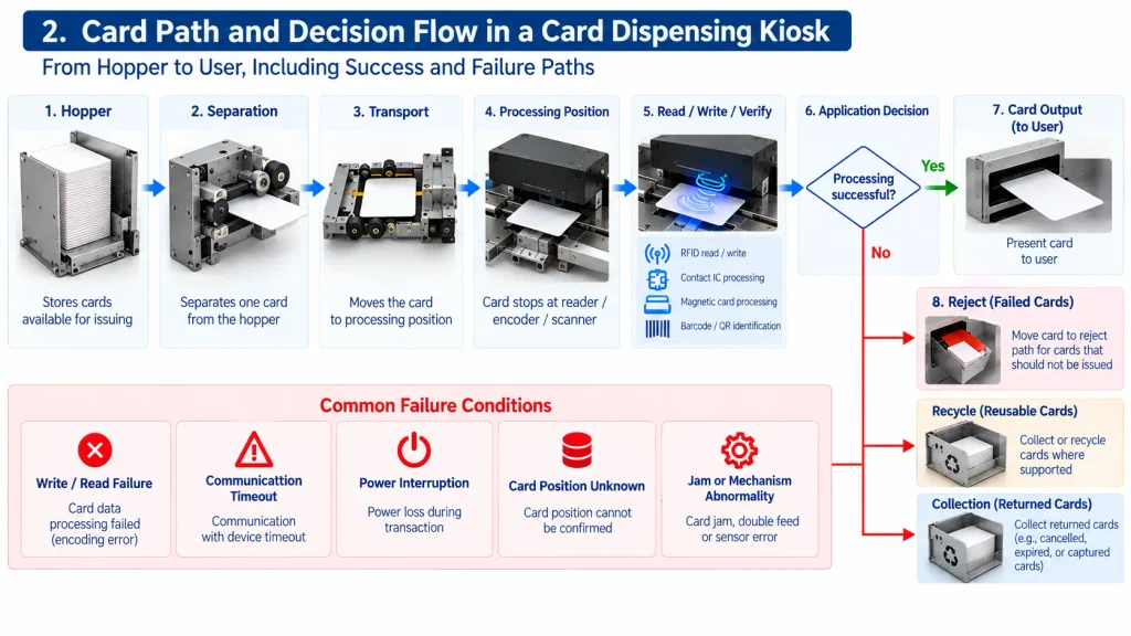
Draw the actual journey of one card:
Hopper → Separation → Transport → Processing Position → Decision Point → Output / Reject / Recycle
Then place the surrounding hardware around this path.
Where does the reader or encoder sit?
How far does the card protrude at the user outlet?
Can a technician reach the card if it stops halfway through the mechanism?
Can the hopper still be removed after the display, printer and power supply are installed?
Where does a failed card go?
Can the reject box be removed without taking the complete dispenser out of the cabinet?
This is the kind of review that is easy to skip when the team focuses only on product dimensions.
In practice, a few extra millimeters of cabinet space may be worth far more than a very compact assembly that requires twenty minutes of disassembly every time a card jams.
Card Output, Reject, Collection and Recycling Are Different Paths
These terms should not be treated as interchangeable.
Card output means the card is presented to the user.
Reject normally means the card failed a required processing step and should not be delivered.
Collection means an inserted or returned card is stored separately.
Recycling means a returned card can re-enter a reusable card workflow where the selected hardware supports it.
Not every dispenser provides every path.
A model intended for straightforward dispensing and collection should not automatically be described as a recycling dispenser.
Likewise, recycling capability should be evaluated together with the intended card workflow, not just from the presence of a return slot.
For parking applications, these differences become particularly important because the entrance and exit terminals may use completely different card-handling architectures. See our parking kiosk hardware integration page for the broader system context.
The Host Controller Connects the Hardware, but the Application Owns the Transaction
A card dispenser may use RS232, USB or another supported interface.
That defines how the host communicates with the hardware.
It does not define the business workflow.
A practical software structure is:
Business Application → Hardware Integration Layer → Device Protocol / SDK → Card Dispenser
The dispenser executes supported mechanical operations.
The application decides when those operations belong in the transaction.
Take the hotel example again.
The dispenser can move a card to the encoder position. It does not know whether the room-key data was written successfully unless that result is supplied through the integrated system.
The application or lock-system integration receives the encoding result and decides whether the next step is:
- present the card;
- reject the card;
- retry the processing step; or
- stop the transaction and request operator intervention.
That separation is important.
Trying to place the complete business workflow inside the dispenser protocol usually creates unnecessary complexity.
For command structure, status handling, timeout logic and recovery behavior, use the separate card dispenser communication protocol guide.
Available development resources can also be found in our card dispenser SDK and communication resources.
Power Architecture Is Easy to Underestimate
The data interface is only one part of the electrical design.
A typical kiosk may contain:
AC Input → DC Power Supply → Industrial PC / Card Dispenser / Printer / Reader / Scanner / Other Peripherals
The card mechanism still requires its specified operating power even if communication is handled through USB or serial.
USB communication does not automatically mean USB power.
When the final kiosk is configured, check peak loads, available PSU capacity, cable length, connector access and the startup behavior of multiple devices.
This becomes more important when the dispenser, thermal printer and industrial PC can all draw higher current during short operating peaks.
Failure Paths Belong in the Architecture
A good architecture drawing should show failed transactions as well as successful ones.
Consider a card that has already left the hopper and reached the processing position.
Then something goes wrong:
- the encoder reports a write failure;
- the reader cannot identify the card;
- communication with one device times out;
- the application restarts;
- power is interrupted; or
- the card remains between two sensor positions.
At that point, the first question should not be:
Which command should we send next?
The first question should be:
Where is the card now?
That distinction matters.
If the software blindly sends another dispense command while the previous card is still inside the mechanism, the recovery logic can create a second problem instead of solving the first one.
For unattended deployment, the software should always be able to recover toward a known physical state or stop safely when the card position cannot be confirmed.
Maintenance Access Is Part of the Hardware Architecture
A prototype can pass every functional test and still be expensive to maintain.
Before approving the cabinet design, check access for:
- hopper refilling;
- card-path inspection;
- reader or encoder replacement;
- reject-box removal;
- cable replacement;
- mechanism removal; and
- manual recovery of a trapped card.
We would not finalize a kiosk enclosure before reviewing these service operations with the actual dispenser layout.
This is particularly important for multi-hopper systems and for hotel encoders mounted inside the card path.
The smallest enclosure is not always the best enclosure.
For an unattended machine, service time is part of the system cost.
How to Choose the Right Card Dispensing Architecture
| Project Requirement | Typical Architecture Direction |
|---|---|
| Issue pre-programmed cards only | Dispense-only architecture |
| Issue and verify RFID cards | Dispenser + reader/writer |
| Hotel room-key issuance | Dispenser + compatible lock-system encoder |
| Return cards without reuse | Issue + collection architecture |
| Return and reuse cards | Recycling-capable architecture |
| Several card products or card types | Dual- or multi-hopper dispenser |
| Barcode-identified cards | Dispenser + barcode / QR scanner |
| Magnetic + IC + RFID processing | Multi-technology reader/writer architecture |
After the workflow is clear, the hardware can be matched against the real project parameters:
- card dimensions and thickness;
- card material and technology;
- hopper capacity and hopper count;
- reader, writer, encoder or scanner requirement;
- host operating system;
- communication interface;
- available installation space;
- required output, reject, collection or recycling behavior; and
- maintenance access.
For SIM-related dispensing projects, the architecture may also include barcode identification, chip processing or multiple card inventories. See our telecom SIM kiosk hardware solution for that application context.
What Should Be Confirmed Before Building the Prototype?
Before moving from CAD into production, the team should be able to describe one complete card transaction without ambiguity.
The card specification should be known.
The hopper arrangement and loading method should be defined.
The reader, writer, encoder or scanner should be selected.
The physical processing position should be confirmed.
The host interface and software responsibility should be agreed.
The successful card path should be known.
The failed-card path should also be known.
And the service technician should be able to reach the mechanism without dismantling unrelated parts of the kiosk.
After that, test the system using the actual card, actual reader or encoder, actual host controller and production-intent software.
A dispenser that feeds cards reliably on a workbench has not yet proved that the complete kiosk architecture is reliable.
Our card dispenser test tools and card dispenser datasheets and manuals can support the prototype and validation stage.
FAQ
What hardware is required for a card dispensing kiosk?
At minimum, the kiosk normally requires a card dispenser, host controller and suitable power supply. Depending on the workflow, it may also require an RFID reader/writer, third-party encoder, barcode scanner, reject or collection box, recycling path and additional sensors.
Does every card dispenser need a reader?
No. A reader is only required when the kiosk needs to identify, read, write or verify the card during the transaction. Pre-programmed cards can be dispensed without an integrated reader.
Can a third-party encoder be installed inside a card dispenser?
In many projects, yes. The encoder dimensions, reading or writing position, card path, communication interface and required card-to-antenna or contact distance must all be compatible with the mechanical design.
What should happen when card writing fails?
The application should first confirm the card position and processing result, then move the card according to the defined failure path. Depending on the selected hardware, that may mean retrying, rejecting, collecting or stopping the transaction safely.
Can the same architecture be used with Windows and Android?
Potentially, yes. The integration method depends on the available interface, protocol or SDK, host ports and operating-system environment. Some projects may use an intermediate controller or industrial PC when direct device communication is not practical.
Who develops the card-dispensing workflow?
SNROKIOSK supplies card-handling hardware and can provide applicable SDKs, communication protocols, test tools, 3D drawings and hardware integration support. The customer’s application team or system integrator remains responsible for the kiosk transaction logic and integration with external systems such as PMS, hotel lock platforms, access-control software or other business applications.
Plan the Card Path Before Choosing the Hardware
The most reliable card-dispensing projects do not begin by asking which dispenser has the largest hopper.
They begin by defining what must happen to one card.
Where does it start?
Where must it stop?
Which subsystem processes it?
What result allows it to continue?
Where does it go if something fails?
How will a technician reach it later?
Once those answers are clear, selecting the dispenser, reader, encoder, controller and enclosure layout becomes much easier.
For a project evaluation, provide the card size and thickness, card technology, required workflow, reader or encoder requirement, number of card types or hoppers, host operating system, communication interface, available installation space and expected output, reject, collection or recycling behavior.
SNROKIOSK can then help evaluate the appropriate card-handling hardware configuration and provide the technical resources required for prototype integration.